RTC INTERFACING WITH AVR
A real-time clock (RTC) is a computer clock that keeps track of the current time. In this tutorial we will discuss about RTC interfacing with AVR.
Synopsis

A real-time clock (RTC) is a computer clock (most often in the form of an integrated circuit) that keeps track of the current time. Although the term often refers to the devices in personal computers, servers and embedded systems, RTCs are present in almost any electronic device which needs to keep accurate time. The Real time clock DS1307 IC basically is stand alone time clock. Well, basically we can use a micrcontroller to keep time, but the value would go off as soon as it is powered off. The RTC DS1307 is a handy solution to keep time all the way, when it is powered by a coin cell. It is uses I²C (Inter-Integrated Circuit) protocol, referred to as I-squared-C, I-two-C, or IIC for communication with the micrcontroller.

Description

Real Time Clock is battery backup power clocks so that it tracks the time even while the computer is turned off, or in low power state. Basically RTC is not a physical clock but is an IC which is present on the motherboard and responsible for timing functioning of the system and system clock. Real Time Clock is responsible to make sure that all the processes occurring in the system are properly synchronized (basically this is task of system clock, but system clock is dependent on RTC, therefore RTC is indirectly responsible for interrupts, timer, task scheduling and synchronization etc.). Today many companies like Philips, ST Microelectronics, Texas Instruments manufacture RTCs There has been a continuous development in RTC, like lowering power consumption, improving frequency stability.

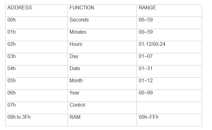
The RTC keeps the date and time arranged in it's memory as shown below:


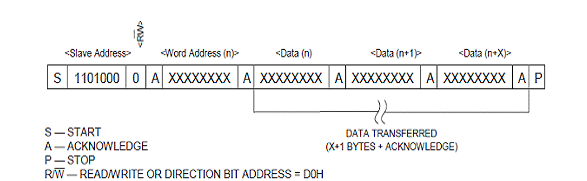
Slave Receiver Mode (Write Mode) 

Serial data and clock are received through SDA and SCL. After each byte is received an acknowledge bit is transmitted. START and STOP conditions are recognized as the beginning and end of a serial transfer. Hardware performs address recognition after reception of the slave address and direction bit (see Figure 5). The slave address byte is the first byte received after the master generates the START condition. The slave address byte contains the 7-bit DS1307 address, which is 1101000, followed by the direction bit (R/W), which for a write is 0. After receiving and decoding the slave address byte, the DS1307 outputs an acknowledge on SDA. After the DS1307 acknowledges the slave address + write bit, the master transmits a word address to the DS1307. This sets the register pointer on the DS1307, with the DS1307 acknowledging the transfer. The master can then transmit zero or more bytes of data with the DS1307 acknowledging each byte received. The register pointer automatically increments after each data byte are written. The master will generate a STOP condition to terminate the data write.

Data Write Cycle


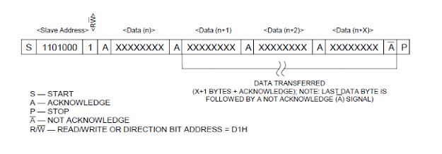
Slave Transmitter Mode (Read Mode)

The first byte is received and handled as in the slave receiver mode. However, in this mode, the direction bit will indicate that the transfer direction is reversed. The DS1307 transmits serial data on SDA while the serial clock is input on SCL. START and STOP conditions are recognized as the beginning and end of a serial transfer. The slave address byte is the first byte received after the START condition is generated by the master. The slave address byte contains the 7-bit DS1307 address, which is 1101000, followed by the direction bit (R/W), which is 1 for a read. After receiving and decoding the slave address the DS1307 outputs an acknowledge on SDA. The DS1307 then begins to transmit data starting with the register address pointed to by the register pointer. If the register pointer is not written to before the initiation of a read mode the first address that is read is the last one stored in the register pointer.            The register pointer automatically increments after each byte are read. The DS1307 must receive a Not Acknowledge to end a read. 

Data Read Cycle


TWI Status Register – TWSR


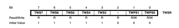
Bits 7..3 – TWS: TWI Status

These five bits reflect the status of the TWI logic and the Two-wire Serial Bus. The different status codes are described later in this section. Note that the value read from TWSR contains both the 5-bit status value and the 2-bit prescaler value. The application designer should mask the prescaler bits to zero when checking the Status bits. This makes status checking independent of prescaler setting. This approach is used in this datasheet, unless otherwise noted.

Bit 2 – Res: Reserved Bit

This bit is reserved and will always read as zero.

Bits 1..0 – TWPS: TWI Prescaler Bits:

These bits can be read and written, and control the bit rate prescaler.

TWI Data Register – TWDR


In Transmit mode, TWDR contains the next byte to be transmitted. In Receive mode, the TWDR contains the last byte received. It is writable while the TWI is not in the process of shifting a byte. This occurs when the TWI Interrupt Flag (TWINT) is set by hardware. Note that the data register cannot be initialized by the user before the first interrupt occurs. The data in TWDR remains stable as long as TWINT is set. While data is shifted out, data on the bus is simultaneously shifted in. TWDR always contains the last byte present on the bus, except after a wake up from a sleep mode by the TWI interrupt. In this case, the contents of TWDR is undefined. In the case of a lost bus arbitration, no data is lost in the transition from Master to Slave. Handling of the ACK bit is controlled automatically by the TWI logic, the CPU cannot access the ACK bit directly.

In Transmit mode, TWDR contains the next byte to be transmitted. In Receive mode, the TWDR contains the last byte received. It is writable while the TWI is not in the process of shifting a byte. This occurs when the TWI Interrupt Flag (TWINT) is set by hardware. Note that the data register cannot be initialized by the user before the first interrupt occurs. The data in TWDR remains stable as long as TWINT is set. While data is shifted out, data on the bus is simultaneously shifted in. TWDR always contains the last byte present on the bus, except after a wake up from a sleep mode by the TWI interrupt. In this case, the contents of TWDR is undefined. In the case of a lost bus arbitration, no data is lost in the transition from Master to Slave. Handling of the ACK bit is controlled automatically by the TWI logic, the CPU cannot access the ACK bit directly.

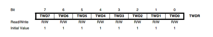
Bits 7..0 – TWD: TWI Data Register

These eight bits contain the next data byte to be transmitted, or the latest data byte received on the Two-wire Serial Bus

Proteus design for RTC interfacing with AVR


Orcad design for RTC interfacing with AVR


RTC Interfacing with AVR

/*  Name     : main.c
 *  Purpose  : Source code for RTC interface with ATMEGA16.
 *  Author   : Gemicates
 *  Date     : 2017-09-07
 *  Website  : www.gemicates.org
 *  Revision : None
 */
#ifndef F_CPU
#define F_CPU 8000000UL          // 8 MHz clock speed
#endif
#include <avr/io.h>
#include <util/delay.h>
#define UCSRA
#define UCSRB
#define UCSRC
#define UDR
#define UBRRL


void init_i2c()
{
TWSR = 0X00;
TWBR = 0X47;
TWCR = (1<<TWEN);
}

unsigned char read_i2c()
{
TWCR = (1<<TWINT)|(1<<TWEN);
while(!(TWCR & (1<<TWINT)));
return TWDR;
}

void write_i2c(unsigned char ch)
{
TWDR = ch;
TWCR = (1<<TWINT)|(1<<TWEN)|(1<<TWEA);
while(!(TWCR&(1<<TWINT)));
}

void start()
{
TWCR = (1<<TWINT)|(1<<TWSTA)|(1<<TWEN);
while((TWCR &(1<<TWINT))==0);
}

void stop()
{
TWCR = (1<<TWINT)|(1<<TWEN)|(1<<TWSTO);
_delay_ms(1);
}

void rtc_write(char dev_addr,char dev_loc,char dev_data)
{
start();
write_i2c(dev_addr);
write_i2c(dev_loc);
write_i2c(dev_data);
stop();
_delay_ms(10);
}

unsigned char rtc_read(char dev_addr,char dev_loc)
{
char ch;

start();

write_i2c(dev_addr);
write_i2c(dev_loc);

start();
write_i2c(dev_addr|0x01);
ch = read_i2c();

stop();
return ch;
}

void tx( unsigned char data )
{
while ( !(UCSRA  (1<<UDRE)) ); // wait until UDR is empty
UDR data;
}

char rx()
{
while ( !(UCSRA  (1<<RXC))  ); // wait until UDR is empty
return UDR;
}

void init_serial()
{
UCSRB (1<<RXEN)|(1<<TXEN);
UCSRC (1<<UCSZ1)|(1<<UCSZ0);
UBRRL 51;
}

void str_serial(char *str)
{
while(*str)
{
tx(*str++);
_delay_ms(1);
}
}


void disp_time_date()
{
char ch;

tx(254);
tx(128);

str_serial("Time: ");

ch = rtc_read(0xd0 , 0x02);
tx(ch/16+48);
tx(ch%16+48);
tx('-');

ch = rtc_read(0xd0 , 0x01);
tx(ch/16+48);
tx(ch%16+48);
tx('-');

ch = rtc_read(0xd0 , 0x00);
tx(ch/16+48);
tx(ch%16+48);

tx(254);
tx(192);

str_serial("Date: ");

ch = rtc_read(0xd0 , 0x04);
tx(ch/16+48);
tx(ch%16+48);
tx('-');

ch = rtc_read(0xd0 , 0x05);
tx(ch/16+48);
tx(ch%16+48);
tx('-');

ch = rtc_read(0xd0 , 0x06);
tx(ch/16+48);
tx(ch%16+48);


}
int main()
{
DDRC =0XFF; DDRD =0XFF;
init_i2c();
init_serial();

rtc_write(0xd0,0x00,0x00);
rtc_write(0xd0,0x01,0x27);
rtc_write(0xd0,0x02,0x08);

rtc_write(0xd0,0x04,0x08);
rtc_write(0xd0,0x05,0x09);
rtc_write(0xd0,0x06,0x13);

_delay_ms(10000); 


while(1)
{
disp_time_date();
}

}

Error message here!

Show Error message here!


Forgot your password?

Error message here!

Send OTP

Error message here!

Show Error message here!


Lost your password? Please enter your email address. You will receive a password you Need.

Send Error message here!


Back to log-in

Close